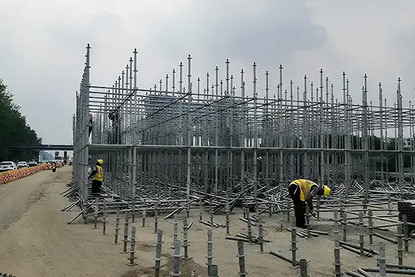
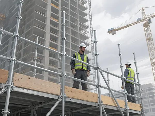
Disc Coupling scaffolding offers numerous advantages including high load-bearing capacity, structural stability, safety and reliability, ease of erection and dismantling, extended service life, and straightforward management. It is widely employed in public construction projects such as bridges, utility tunnels, underground railways, large industrial buildings, major stages, and sports venues.Today we shall provide a brief overview of the erection, construction, dismantling, and acceptance procedures for the core component of disk-coupling scaffolding systems: the disk-coupling support frame.

Safety Requirements for Erecting Disk-Coupled Scaffolding
Structural safety has always been the foremost objective in the implementation of construction projects, particularly for public buildings, where it is essential to ensure that structures remain safe and stable during seismic events. The safety requirements for erecting disk-coupling scaffolding are as follows:
1. Erection must strictly adhere to the approved plan and requirements outlined in the site briefing. Cutting corners is strictly prohibited. Rigorous compliance with erection procedures is mandatory. Deformed or previously straightened uprights must not be used as construction materials.
2. During the erection process, a qualified technician must be present on site to supervise the work, with a safety officer conducting inspections and oversight throughout.
3. During erection, overlapping operations at different levels are strictly prohibited. Effective measures must be implemented to ensure the safe transfer and use of materials, fittings, and tools. Depending on site conditions, safety marshals shall be stationed at access points and above/below work areas to provide supervision.
4. Construction loads on the working level shall comply with design requirements and must not exceed specified limits. Materials such as formwork and reinforcing steel shall not be concentrated in piles upon the scaffolding.
5. During the period of scaffolding use, unauthorised removal of structural members from the framework is strictly prohibited. Should removal be necessary, approval must be sought from the technical supervisor, and remedial measures must be confirmed before proceeding.
6. Scaffolding shall maintain a safe clearance from overhead power lines. The installation of temporary site electrical circuits and the implementation of scaffolding earthing and lightning protection measures shall comply with the relevant provisions of current industry standards.
7. Regulations for Working at Height:
- ① Scaffolding erection and dismantling operations shall cease during gale-force winds of force 6 or above, heavy rain or snow, or dense fog.
- ② Personnel shall use ladders to ascend and descend scaffolding. Climbing the framework is prohibited, and the use of tower cranes or hoists to lift personnel up or down is strictly forbidden.
Construction Process Flow for Disk-Coupled Scaffolding
When erecting disc-coupling scaffolding, vertical uprights should be installed first, followed by horizontal beams, and finally diagonal braces. Once the basic scaffolding unit is formed, this unit is then expanded to construct the complete scaffolding system.
- Foundation Treatment
- Surveying and Layout
- Installation of Base Plates and Levelling Adjustment
- Installation of Uprights, Horizontal Members and Diagonal Braces
- Erection in Accordance with Construction Drawings
- Installation of Top Supports
- Elevation Adjustment
- Laying of Primary and Secondary Joists
- Installation of Safety Measures
- Formwork Installation
- Inspection, Acceptance and Documentation
Key Control Points for Erecting Disk-Coupled Scaffolding
1. Lay out accurately according to the dimensions specified on the support frame configuration drawings. The erection scope shall be determined by the design drawings or as specified by the Client, with ongoing adjustments made as the support frame is erected.
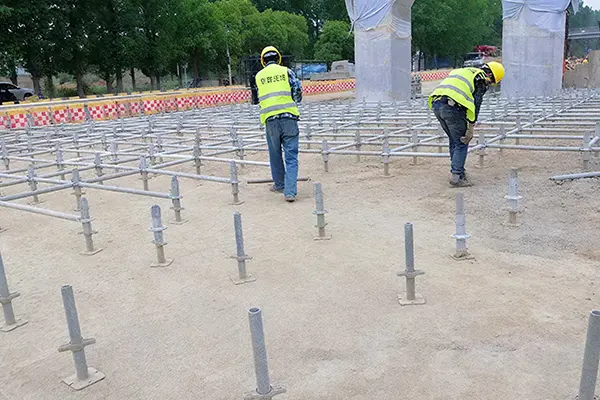
2. After laying out the foundation, position the adjustable baseplate in the designated location. When positioning, pay attention to the baseplate’s underside; materials with an uneven baseplate are strictly prohibited. The baseplate wrench may be pre-adjusted to approximately 250mm from the baseplate to facilitate elevation adjustments during erection. Slide the main frame sleeve of the standard base upwards onto the adjustable base, ensuring the lower edge of the standard base is fully seated within the recessed groove on the wrench’s load-bearing surface. Position the crossbar casting head over the small hole in the disc, aligning its front end against the main frame’s round tube. Secure the assembly by inserting a wedge through the small hole and hammering it firmly into place.
3. After installing the sweep bar, level the entire scaffold structure to ensure it sits on a single horizontal plane, with horizontal deviation of crossbars not exceeding 5mm. The exposed length of the adjustable base’s threaded rod shall not exceed 300mm. The height of the lowest horizontal bar serving as the sweep bar from ground level shall not exceed 550mm.
4. Arrange vertical diagonal braces in accordance with the scheme requirements. In compliance with regulatory standards and considering the actual on-site erection conditions, vertical diagonal braces are typically arranged in two configurations: a matrix-type spiral pattern (i.e., lattice column form) and a symmetrical figure-eight arrangement (or symmetrical V-shape). Implementation shall be guided by the scheme.
5. Adjust and inspect the verticality of the scaffolding structure as the erection height increases. The permissible deviation for verticality at each scaffolding level (1.5m height) is ±5mm. The permissible deviation for overall verticality of the scaffolding structure is ±50mm or H/1000mm (where H is the overall height of the scaffolding structure).
6. The cantilever length of adjustable support brackets extending from the top horizontal bar or double-channel steel support beam must not exceed 500mm. The exposed length of the threaded rod must not exceed 400mm. The insertion depth of adjustable support brackets into the upright bar or double-channel steel support beam must not be less than 200mm.
7. Structural measures such as column bracing and tie-in arrangements shall comply with the design specifications.
Specification for Phased Inspection and Acceptance of Disk-Coupled Scaffolding
Upon reaching the design height for the scaffolding tower erection and prior to concrete pouring, the following key aspects of the disk-coupling support frame shall be inspected:
- 1. Foundations shall comply with design requirements and be level and solid; there shall be no loosening or suspension between uprights and foundations;
- 2. The three-dimensional dimensions of the erected scaffold structure shall conform to design specifications. Erecting methods and the installation of diagonal braces shall comply with regulatory requirements;
- 3. The cantilevered projection length of adjustable support brackets and adjustable bases beyond horizontal members must meet design-specified limits;
- 4. Verify that the pin plates on vertical diagonal braces are securely fastened and parallel to the upright posts; ensure pin plates on horizontal members are perpendicular to the horizontal members;
- 5. Verify that the installation locations, quantities, and configurations of all components comply with design specifications;
- 6. All pin plates on the support frame must be in a locked position; cantilevered sections must be accurately positioned. Horizontal and vertical diagonal braces for each stage must be fully installed with pin plates securely fastened, and all safety protections must be in place;
- 7. Corresponding safety measures, such as horizontal safety nets, must comply with the requirements of the specialised construction plan;
- 8. Construction records and quality inspection records for the erected structure must be timely and complete.

Precautions for Dismantling Disk-Buckle Support Frames
1. Concrete and prestressed duct grouting shall only be dismantled after achieving the design strength and passing inspection.
2. The dismantling of support frames must be verified through calculations and comply with relevant regulations. The timing of formwork removal shall be strictly controlled, with a formal dismantling application submitted and approved prior to commencement. Frame removal shall proceed in accordance with the sequence specified in the construction plan.
3. Prior to dismantling the scaffolding, a designated person shall inspect whether all materials and debris have been cleared from the structure. A safety zone must be demarcated and conspicuous warning signs erected before commencement. A dedicated individual shall maintain a security cordon; no other personnel shall be permitted to work beneath the structure during dismantling operations.
4. When dismantling scaffolding towers, adhere to the principles of top-down, later erected first dismantled, and step-by-step clearance (i.e., commencing from areas exhibiting greater deflection). The sequence for component removal shall be the inverse of the erection sequence, with simultaneous dismantling at different levels strictly prohibited. The dismantling sequence shall follow the principles of full-bay, multi-point, symmetrical, uniform, and gradual removal: commence with the central bay before proceeding to the side bays, dismantling the support frames symmetrically from the bay centre towards both end supports.
5. Partial demolition or simultaneous upper and lower stage demolition is not permitted. Ensure thorough sequential demolition, clearing one stage at a time, and clearing one pole at a time.
6. When dismantling the support frame, to maintain structural stability, the height-to-width ratio of the smallest remaining section must not exceed 3:1.
7. When dismantling steel pipes and fittings, the pipes and fittings must be separated. It is not permitted to transport pipes to the ground with fittings still attached, nor to remove and transport two pipes simultaneously.
8. When dismantling scaffolding planks, they shall be erected and transported from the outer edge inwards to prevent planks and debris from flipping outward and falling from height, thereby causing injury.
9. During unloading, personnel shall pass each component down to the ground in sequence; throwing components is strictly prohibited.
10. Scaffolding components delivered to the ground level shall be promptly inspected, repaired and maintained. Contaminants on poles and threads must be removed; severely deformed components shall be returned for rectification. Following inspection and rectification, components shall be categorised by type and specification for storage and kept in good order.
11. When dismantling structural members, personnel must communicate with one another and coordinate their work. Loosened components must be promptly removed and transported away to prevent accidental leaning or support.
12. Upon completion of the day’s work, thoroughly inspect the immediate vicinity of the workstation. Should any areas presenting potential hazards be identified, promptly rectify them or continue working until a complete procedure or section is satisfactorily secured before leaving the workstation.
Summary
The bolted-coupling support system features a fully standardised and modularised series of components. To accommodate practical construction requirements, the spacing between vertical post coupling nodes is set at 0.5m increments, while horizontal cross-bar lengths are configured in 0.3m increments. This enables the assembly of multiple frame dimensions, facilitating curved configurations. The system can be erected on sloping or stepped foundations and is capable of supporting stepped formwork.
Additionally, the disk-coupling support system can be temporarily employed for numerous other purposes. For instance, it may serve as a secure passageway for vehicular traffic; it can be utilised as a double-row scaffolding system; it enables the rapid erection of temporary working platforms; when combined with clip-on step ladders, it swiftly forms a safe, reliable cage ladder access route facilitating personnel ascent and descent; moreover, it can virtually replace ordinary steel tubing in all its applications.
As a novel form of scaffolding, the disc-coupling support system offers structural safety and reliability in project construction, with swift and convenient assembly and dismantling. It features no loose components and is easily managed. Compared to traditional scaffolding, it demonstrates clear advantages in both engineering safety and quality, as well as in promoting civilised construction practices. Consequently, it has been widely promoted and adopted in numerous regions.


